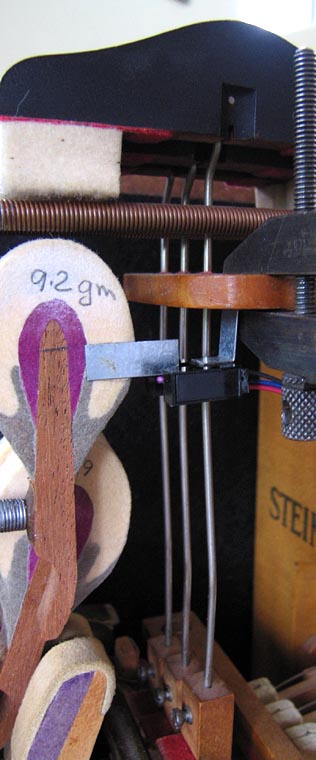
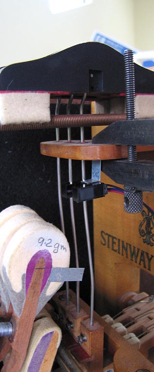
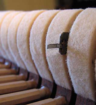
Test setup: left picture: The hammer is in its rest position. The flag on the hammer is a piece of 22 gauge flashing 6.5 mm tall. It is adhered to the side of the hammer with hot-melt glue. The opto-sensor is suspended from the damper guide rail with another piece of flashing adhered to the opto with -- you guessed it -- hot melt adhesive. The parallel-jaw clamp secures the flashing to the damper guide rail. right picture: Here the flag has passed through the opto gate. The hammer is not checked, but is where it stops when the key is fully dipped. |
 |
|
|---|---|---|
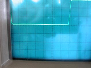
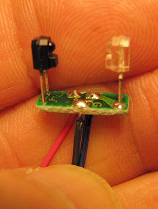
left picture: This is a very crude 1-second hand-held exposure of the Tek scope screen. Horz axis is 0.1 ms/cm; Vert sens is 5 v/cm. This particular ffff blow measures 0.68 ms for a flag velocity of 9.6 meter/sec. The hammer molding velocity, after geometry correction, was 8 meters/second. right picture: drawing & schematic of opto-sensor, and measurement circuit. |
 |
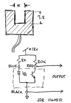 |
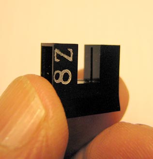
left picture: The innards of the opto sensor. The black case houses the photo-transistor, while the clear case houses the LED. right picture: The opto housing. The slot (vertical in this picture) is 0.5 mm wide. I designed this opto pair for HP. The slot had to be this wide in order to capture enough of the LED illumination because of the very wide 5 mm gap between the two legs. |
 |
 |
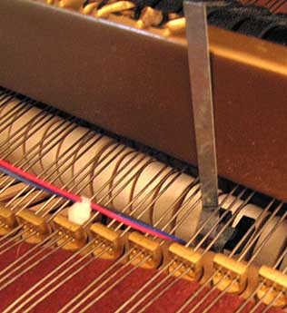
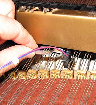
Installation in Steinway "M" left picture: The opto -- on its supporting strip of galvanized flashing -- is in place between two unisons. The strip will be clamped to the capo. right picture: Inserting the opto between the unisons. |
 |
 |
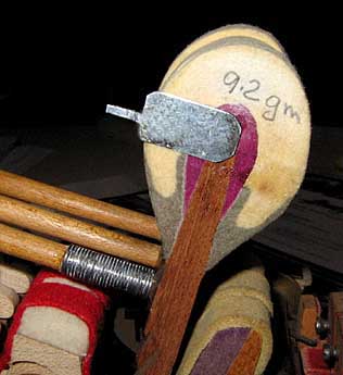
left picture: Flag installed on note E4 of S&S model "M". The flag is read about 6 mm below string contact. right picture: The flag hot-melt-glued to the side of action model hammer.
|
 |
 |
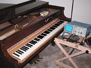
left picture: Measurement setup for S&S "M". A fff blow clocked at 5.5 meters/second.
|
 |